Building an adding machine in a prison building game
As of late, I really got into Prison Architect. It’s a fantastic game - you get to plan your own prison just the way you like, decorate it and then see how it fares when ‘actual’ prisoners are living there. Also, its DLCs are somewhat fair-priced, which isn’t usually the case with Paradox’s games. I wanted to do something unique to express my appreciation of the game, so I built a simple calculator in it.
The plan
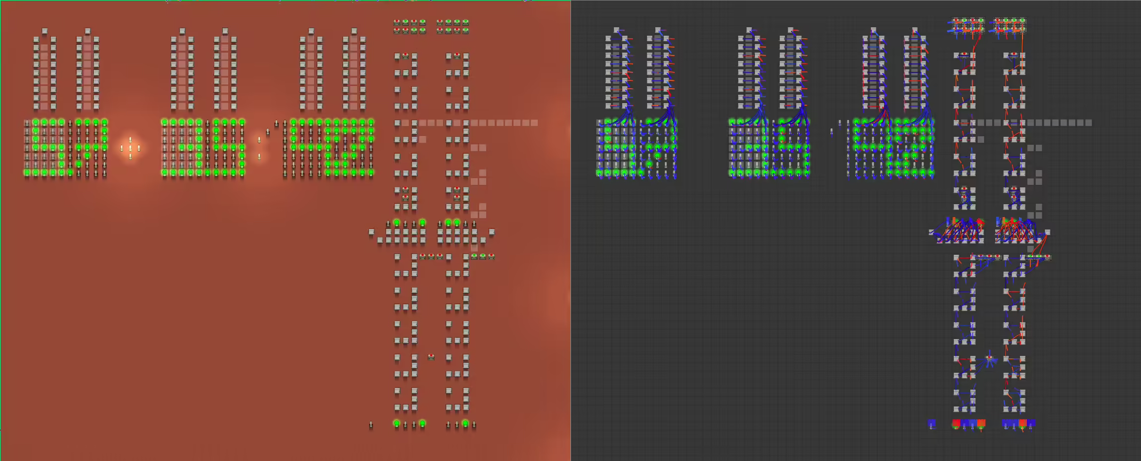
Luckily, the game features a logic gate system, so we don’t need to figure out how to simulate one using game mechanics. There’s also a ‘status light’ object which lights up when it receives a signal, so we’ll use that as a building block of a display. There’s no way of cloning logic gates etc. with its connections to other utilities, so since I don’t really want to spend eons on connecting magical boxes in a video game (yet?), we’ll limit our calculator’s capabilities to adding two numbers with two binary coded decimal digits. That means our calculator will be able to add 99 and 99 at most, so we’ll actually need three digits on the result display (something I’d figured out way after I built the displays and connected them…).
I picked BCD as the encoding, because the only way of displaying plain binary numbers in decimal I could figure out was to connect each possible combinations of bits to AND and NOR gates, then connect the NOR gate to the AND gate, to then connect the AND gate to the display in a proper way. That means I’d have to mindlessly map about 99 + 99 + 198 = 396 possible outcomes onto the displays. With BCD, the number of possibilities goes down to 10 + 10 + 10 + 10 + 1 + 10 + 10 = 61, since I only need to connect each digit representation with its display and the first digit of the result number can only be either 1 or 0.
You can add BCD digits with conventional binary adders, but you might need to convert them later by adding six to the result and sending the carry bit to the next digit’s adders (if that makes sense). Since each BCD digit uses four bits, in order to add the digits, we’ll need four full adders connected together forming a ripple carry adder (I think). Although four adders is enough, our big adder will consist of five small adders, since if the last adder outputs a carry bit, we will have an integer overflow. The additional circuit allows us to incorporate the bit into the computation’s result. Later, we’ll setup a bunch of NOR gates connected with AND gates, which will be connected to the output of the big adders, that will output signal to another set of two big adders that will preform the conversion, if required.
Normally we’d need some-kind of a flip-flops to build a keyboard with, but the game features an object that emits signal constantly, so we’ll just use it.
Adders
We can easily implement a full adder with the game’s logic gates. We can then place four more adders underneath it, connecting them together to form the big guy. Since, for some reason, most in-game emitters send a high signal by default, we should also connect a turned off lever to the first adder’s carry input gates, and two turned off levers to the ‘screw overflow’ adder’s input. We also connect each adders output (the XOR gate) to a corresponding light at the bottom. We could directly connect the outputs to the next part, but I think it would make the build less clear (click the image to rotate)
Next, I connected the lights to a bunch of NOR and AND gates, and these to an OR gate, so that the ‘circuit’ outputs signal only if the output lights form a binary number that is greater than nine. The signal then turns on the switches that are connected to a next big adder that adds six to a digit only when a high signal is emitted. However, these adders are different from the previous ones, because the final adder of the first big adder passes its carry bit to the first full adder of the next ripple carry adder. And the last full adder of the second big adder passes its carry bit to the leftmost bit of the output.
Screen
The display is a straightforward beast: the rows of lights under the BCD converter are appropriately mapped to a bunch of NOR and AND gates, the NOR gates are inputted into the appropriate AND, so that when the AND gate emits a signal, lights corresponding to the appropriate digit light up:
The light that corresponds to the hundreds digit of the sum is directly connected to the display, since it doesn’t need this kind of a dashboard.
Demonstration
Since I don’t really know much about electronics, feel free to contact me if you think there’s an error in the article or if you feel like something is badly worded.


